 will stedden
RASER Week 1: LED circuits
In this lesson we'll learn how the electricity lighting up our gadgets flows through wires from batteries.
My friend Pete built this amazing Jacob's ladder that we'll use to start off the lesson. The arc of light traveling up the Jacob's ladder is ionized air, just like in a lightning bolt. Electricity flowing from one wire to the other causes the air itself to emit light.
The students will grapple with the flow of electricity hands on by making an LED light up. Here's the battery connected to the LED to make it glow.

Electricity flows out of the battery and into the material in the LED. That material is specially designed so that when electricity tries to pass through it, the material glows. This is kind of like the air in the Jacob's ladder lighting up
Getting started with circuits
Next, we move on to building our own simple circuits that light up. The first component, the breadboard, is where all of the electronics construction takes place. You use the breadboard to connect circuit components together.

This breadboard has the back removed so you can see the way all of the holes are connected on the reverse side. On the outsides, the plus and minus holes are all connected. In the center, the numbered rows are connected. Plugging into a connected hole is just like touching those to wires together directly.
The LED circuit
Now that we're acquainted with the breadboard we're going to build the basic LED circuit. First, start by connecting the plus and minus end of the battery to the plus and minus rows of the breadboard.

Next, insert the long wire of a clear LED into the plus terminal, and insert the short wire into the minus terminal. The LED should light up. If it doesn't try reversing the ends. Remember that the longer wire should stick into the plus side. This is because the LED only lets the electricity flow in one direction.
Drawing the circuit
We can draw the flow of electricity from the battery into the LED and then back into the other end of the battery. This is called a circuit diagram, and it helps us to picture how the circuit works and how to modify it to make new things.

Electricity leaves one end of the battery and tries to get back to the other end. On its way around, the electricity flows out of the battery on the left and into the LED on the right. Then it leaves the LED and continues around the rest of the loop.
Using different colors
The blue LED could be hooked up directly to the battery because the LED requires the same amount of electricity that the battery supplies. The yellow, green, and red LEDs need less power so we have to reduce the amount of electricity getting to them from the battery. To do this, we need to add a resistor, which burns up some of the electricity inside of it.
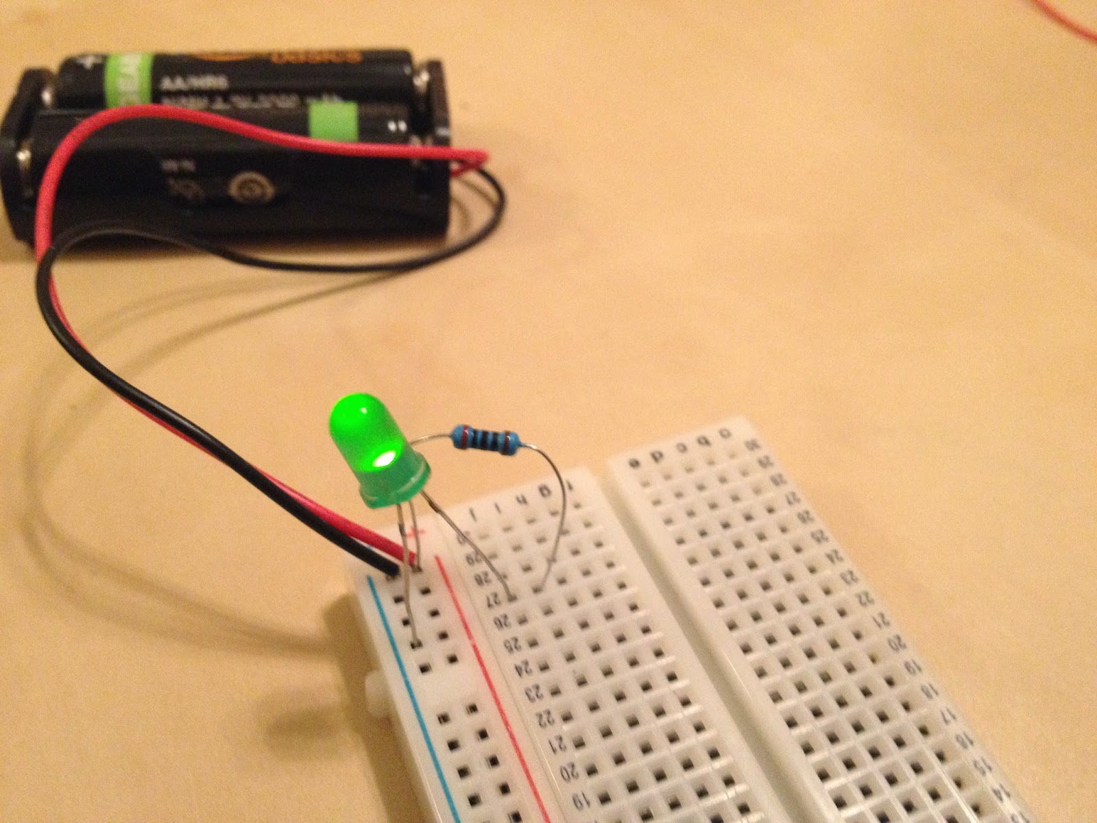
The green LED will still work without the resistor, but it will be lit more brightly than it should. Without the resistor, the green LED will burn out after a while. The resistor protects the LED from getting too much power at once. To learn more, see this article.

Two LEDs side by side
If we want to power multiple LEDs at once, we can put them both into the circuit next to each other. Make sure that the long ends are both connected to the resistor and that the short ends are connected to the minus end of the battery. This is called putting the LEDs in parallel. You can try putting one LED after the next (in series), but that keeps the battery from being able to light them.

Now we can redraw this circuit just like before.

Quick Quiz
As a quick test, let's ask what would happen if we unplugged one LED from the two LED circuit. Will the other LED still work? If we go back to the circuit diagram we see that electricity can still flow through the other LED even if the first one is removed. Try it out to see what happens.
LED lightning game
To end the lesson, let's try to play a game. This game will give us practice building LED circuits.
Since we know how to put multiple LEDs together, try to light the right number to answer a question. Ask a simple math problem and then build a circuit with that number of LEDs lit up. Then ask a new math problem and modify the circuit to get the right number of LEDs again.
As you go, try making the circuits more modular so you can modify them quicker. Try to incorporate simple switches so that you can change the setup faster too.